01 02 03 04 05 06 07 09 10 12 13 16 20 26 30 31 32 39 41 42 43 47 48 49 53 54 55 59 61 62 63 64 65 66 67 69 70
On three Olympus OM camera bodies there were noticeable sharpness differences between viewfinder and film. This is tested by placing a transparent plate on the film rails and looking through the camera's lens with a telescope. Adjustment is made with thin paper and metal strips, between focusing screen and its seat, below the bayonet mount, and/or by filing the rests where the bayonet mount sits on.
I always were in doubt if the sharpness of my pictures was at optimum. I've tried many lenses and films in my OM Cameras. By comparison of negatives and slides in a 48x enlarging microfilm viewer, I found out a lot about their differences. But this did not show where errors come from – you only see the net result of many components. How can I check the camera body itself? And how the lenses? Here's what I've learned while trying this.
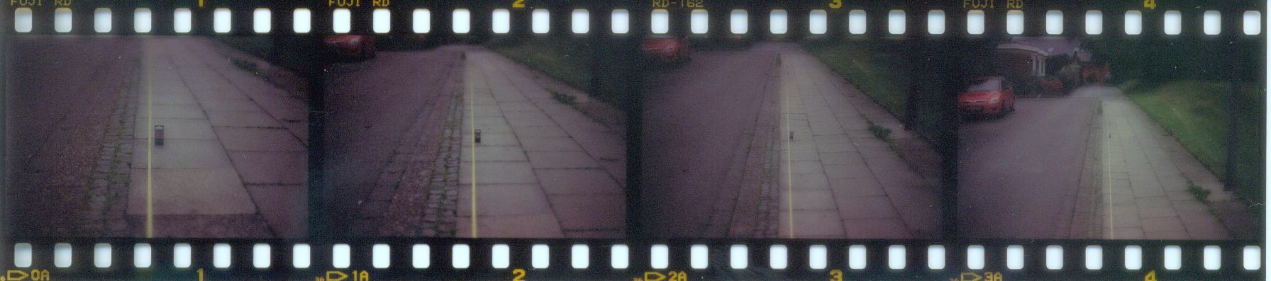
My suspicion was that focusing could be better. So I put a loong meter tape on the ground, placed a small box beneath, and did my best on focusing on the box.
(Sorry for the scan quality. I found no cheap wet mount drum scan. )
The resulting slides showed that not the box was at optimum sharpness, but instead a distance 1/5 part in front of the box!!
Obviously, the focussed distance in the viewfinder was not in coincidence with the film plane. This is quite noticeable when you shoot at f/4 or faster!
The OM Service Manual says that the distance between film plane and lens mount (Backfocus) should be 46 +/- 0,02 mm. I tried measuring this
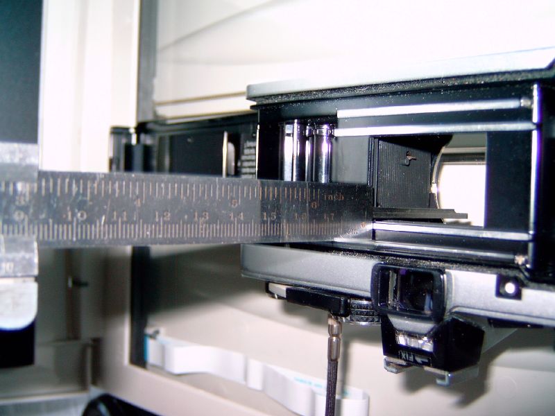
but didn't have the right equipment so that my error was much too large. Anyway, it seemed to be more at 46,2 mm in one and 46,1 mm in another OM camera body. Maybe that's why I can focus my lenses a bit beyond infinity.
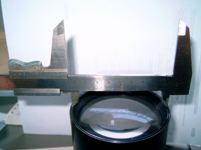
I found a better use for my old calipers – it's a nice tool to unscrew lenses ;-)
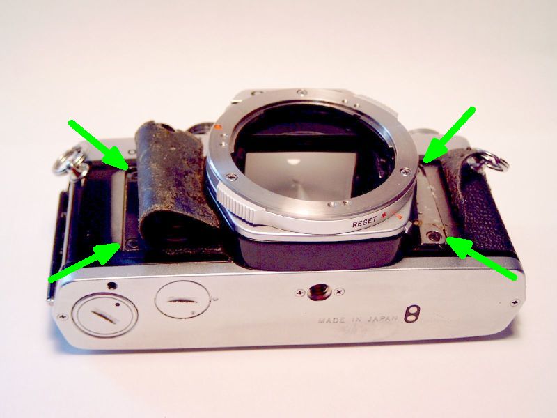
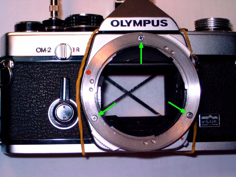
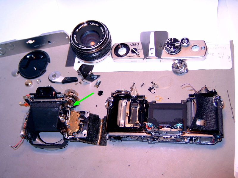
So the measure was ten times out of factory tolerance. The service manual recommends putting thin washers between front and main chassis. This means peeling off the leather and unscrewing those four screws marked with green arrows.
Such washers were available from Olympus in thickness from 6 um up. But this will worsen my too large a distance, and will do nothing against differences between film and viewfinder, as it affects both the same way. And unfortunately, according to the manual, special adjustment tools are required. I had to find another way.
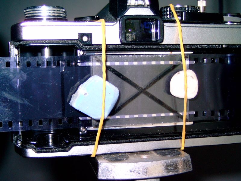
My first idea was to reverse the way the light takes during exposure. I took a piece of black-and-white negative film with contrasty test patterns
and placed it in the camera where it belongs. With the matte emulsion side to the lens, of course.
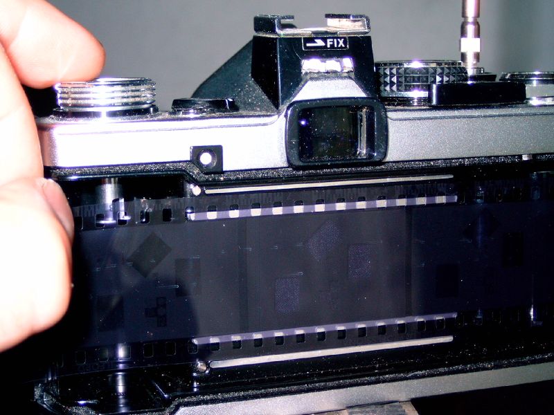
Usually, this is held down by the rear cover's pressure plate to the right of the funny text:
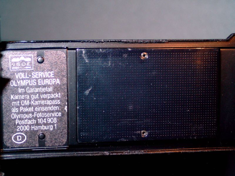
But we will need a piece of translucent material instead.
Check that it is absolutely flat!
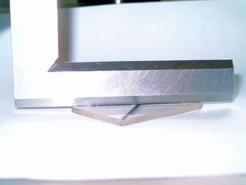
I used parts lying around to hold everything in place:
If this pressure plate fits over the outer film rails, it will act just like the original. I made it a bit smaller, 50x35 mm, fitting *between* the outer rails. In the picture, it sits on the inner film rails, which are made 0,2mm deeper, for easy film transport. But the plate may be tilted a bit so that its edges sit on the outer rails, leaving the film a bit loose, in just the same condition as during exposure .
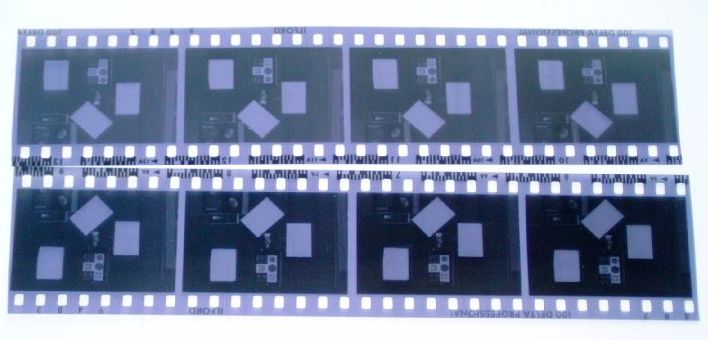
On the negatives, there were different test patterns. The one below contains 36 black and white line pairs. They get increasingly finer towards the centre.
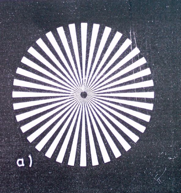
I photographed this subject from 2m distance so that the whole circle is 1.5 mm wide on the negative. This can be seen much enlarged with the test set-up described below.
Due to limited resolution of lens and film, the finest lines in the middle merge and get indistinguishable. For a quantitative number, one may measure the diameter of this fuzzy grey disc and calculate a lp/mm value. On the negative, it's 11.5 divided by the diameter in millimetres. On your monitor, divide the diameter of the whole circle by that of the inner fuzzy area and multiply by 7,6. I didn't include the big pictures of the whole circle here, but found values between 30 and 40 lp/mm. This is so-so, maybe enough for unambitious photography, but much less than the lens can resolve. Definitively, potential is wasted here.
This is it on Ilford Delta 100:
The same subject on Technical Pan (no longer made by Kodak):
Note that the edges are much better defined on Technical Pan and that the image has less noise. But the diameter of the fuzzy centre is almost the same on both films. It isn't the film that is limiting resolution, but instead the optics. Therefore I could not use these negatives for critical testing: they were not sharp enough. And I did not want to spend a lot of money for commercial-made test patterns.
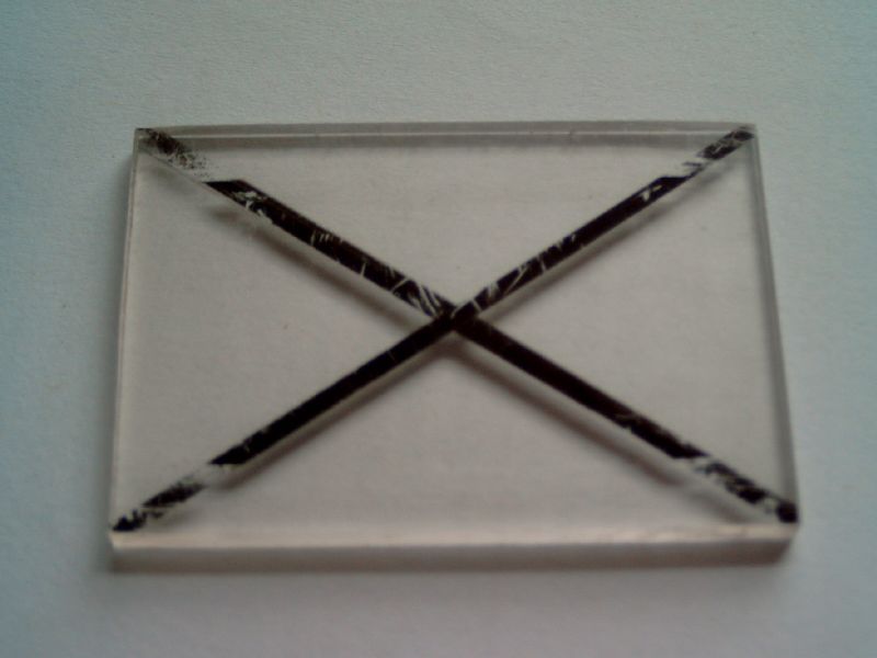
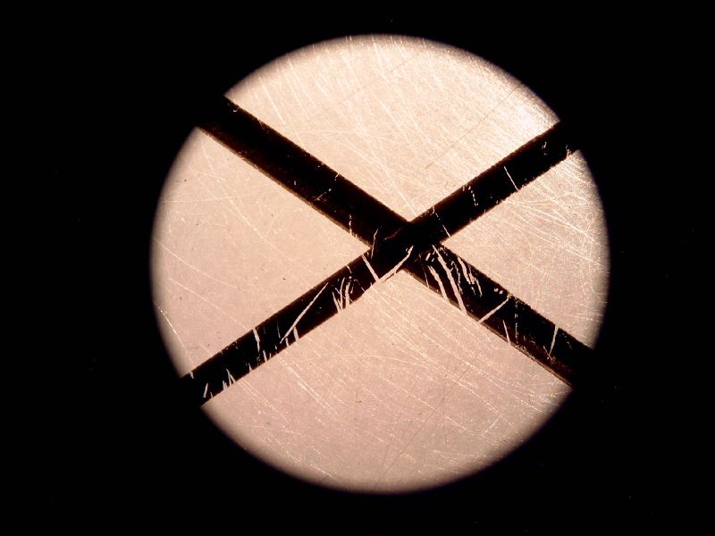
In the next try I used my transparent pressure plate alone. To get rid of doubtful film flatness issues, I placed it directly onto the lower film rails. And that's why there are those badly scratched diagonal black ink lines: they replace the picture as they lie in the same plane as the film emulsion. Where they cross is the middle of the image area. They too allow to check the edges of that area. Furthermore, you don't have to worry about getting a real sharp test negative! The ink has a lot of tiny holes, which are very well suitered for testing image quality.
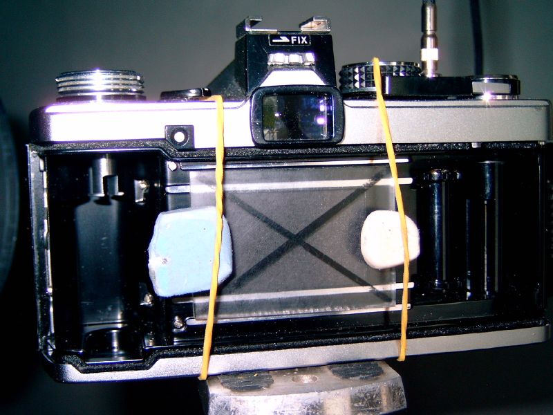
Now let's shine light through all this! The camera will have to be set to B and the shutter kept open with a cable release.
Looking through the lens, you will see the negative or the ink lines. Their enlargement is 250 mm (standard viewing distance) divided by the focal length of the lens. In this case, 250mm/50mm = 5 times.
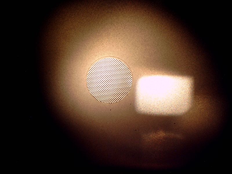
Letting the shutter close, you will instead see the focusing screen, lit through the tiny viewfinder opening. The bright square is the lamp and the round spot is the microprism ring.
However, eyes can accommodate to any other distance than the 250 mm standard. So there is little difference to the naked eye if you turn the focusing ring of the lens. And 5 times magnification is much less than a good negative can be enlarged. For critical testing, the magnification should be a few times higher than for the biggest enlargement ever used in pictures. Something between 30 and 100 times total magnification may be right. So we need another optics to get additional 6 - 20 times enlargement.
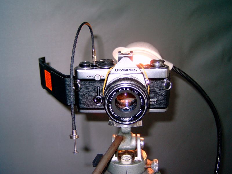
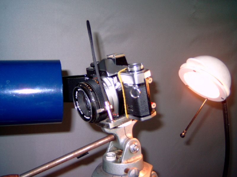
Ed Romney once patented to use another camera with a long telephoto lens for that purpose. Binoculars or telescopes work as well. I own one with 28x enlargement (telescope focal length divided by that of the eyepiece), which is a bit high. But more important is that the telescope's lens diameter is bigger than the camera lens, and that its centre is unobstructed. Mirror telescopes therefore don't work for this.
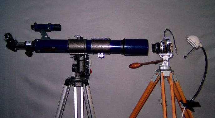
Now get outside and focus the telescope to infinity. Several kilometres distance will suffice. NEVER LOOK INTO THE SUN with remaining eye!!! Mark that adjustment on the telescope. In my case, this was not too critical, as can be checked later in the test set-up by changing this focus a little. This also indicates that the telescope quality isn't critical.
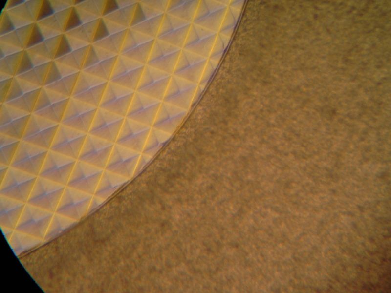
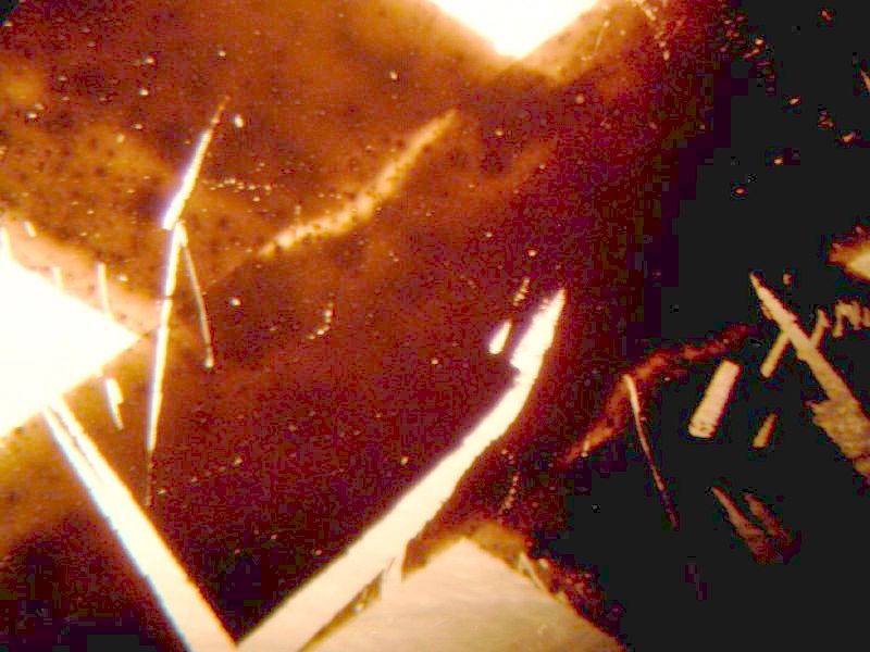
The telescope is now ready to be placed in front of the camera. The camera is to be set to infinity, too. Their distance is unimportant, as the light for infinity adjustment runs in a parallel beam between both. My major problem was to reach the camera lens with one arm while peering into the telescope's eyepiece! The 45 degree "Zenith" mirror at the left end of the telescope tube was a big help. This is what can be seen in the telescope.
The structure top left is a section of the focusing screen's micro prism area. The rest is a part of its matte surface. Focusing the camera lens now is VERY critical to the sharpness of the picture. It seems even possible to focus differently on the lower or on the higher parts of the matted surface! The most exact way I found is to take a split-image focusing screen and focus on the middle of the split. Turning the focus ring of the lens half a millimetre makes a noticeable difference. This sensitivity is comparable to my focusing efforts when photographing under critical conditions.
Below is another lens at optimal focus. Note how the coloured edges of the micro prisms change from red-green to blue-yellow. Obviously, colour correction is different with this lens.
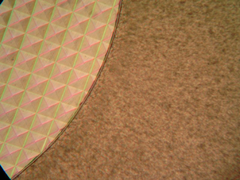
This is what you see when focusing the camera to closer distances. The circles are the Fresnel lens' structure on the bottom of the focusing screen. They get thicker to the edges of the screen.
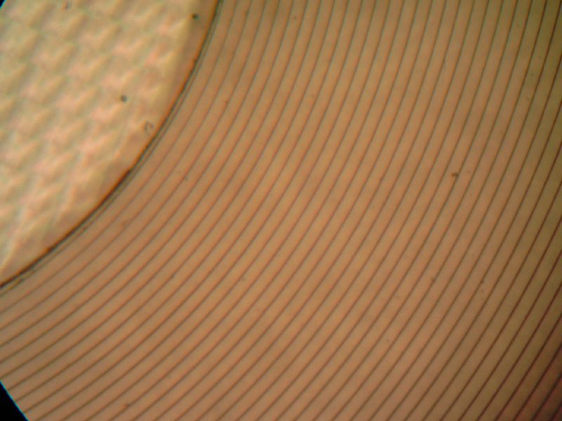
If they were of equal height (I'm not quite sure), they should be seen equally sharp in the whole image area. If some sides differ in sharpness, then lens and screen aren't parallel. Turning the camera sideways or tilting up and down is all you need to explore the edges.
This is the fresnel structure at one edge. It's tricky not to confuse which one you are really looking at. Hold your finger over the film plane and look out for the shadow it casts, to find out where you are.
Now let's focus to infinity again somewhere near the focusing screen's centre.
Opening the shutter then reveals the enlarged image of the ink lines on the transparent plate. Their edges, scratches and holes should appear sharp, too!
Turning the camera's focus a little gives a feeling what the best position is.
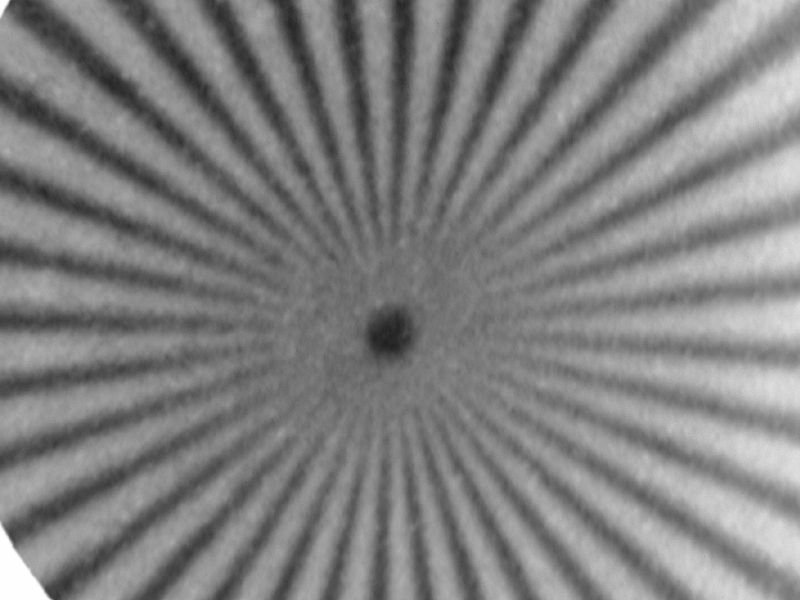
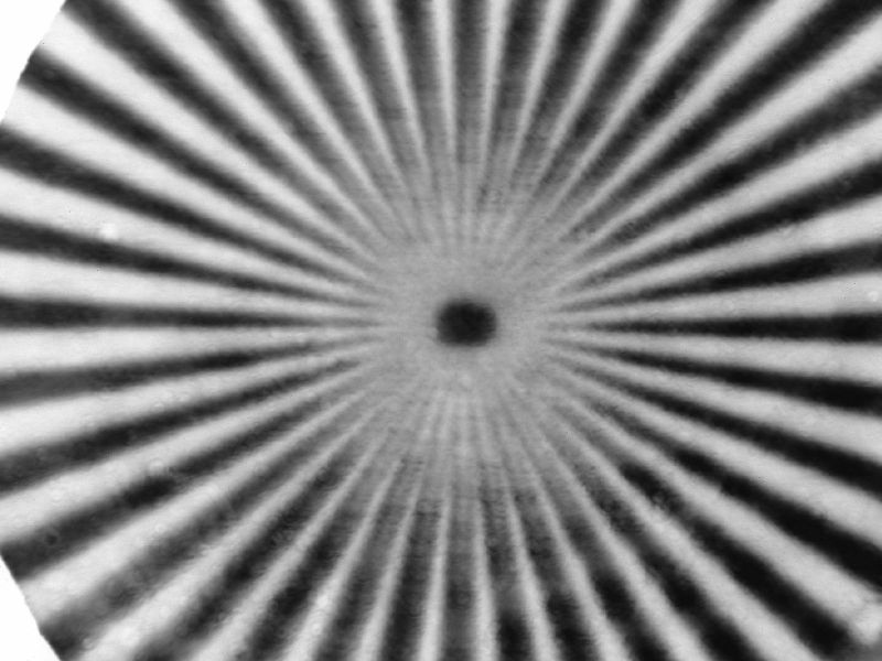
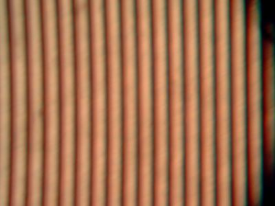
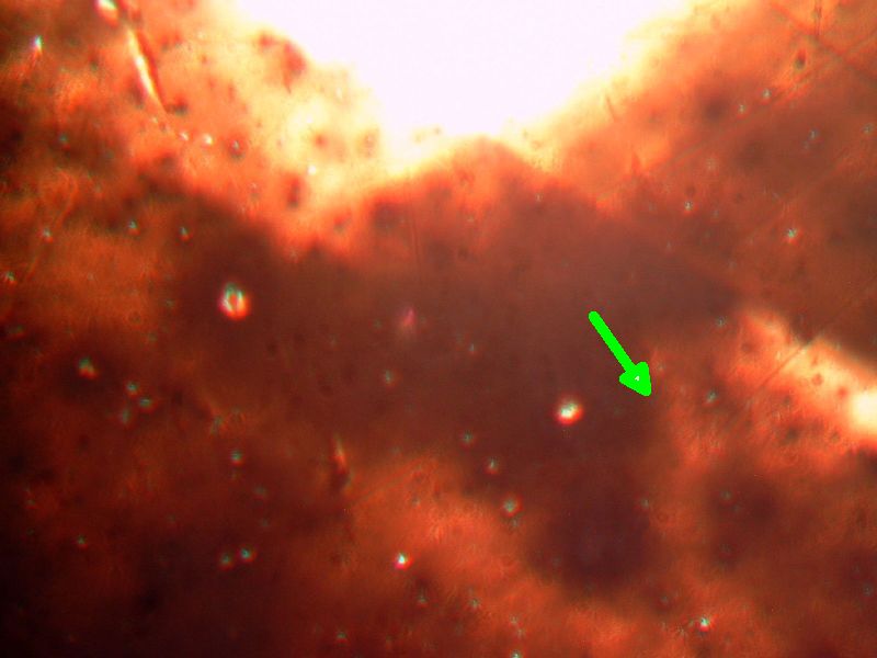
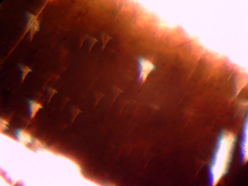
If too close, it may look like this:
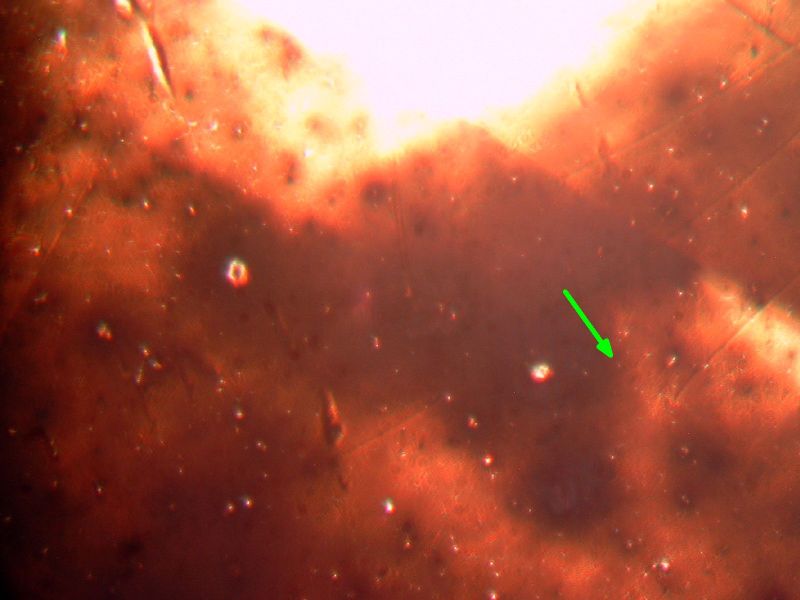
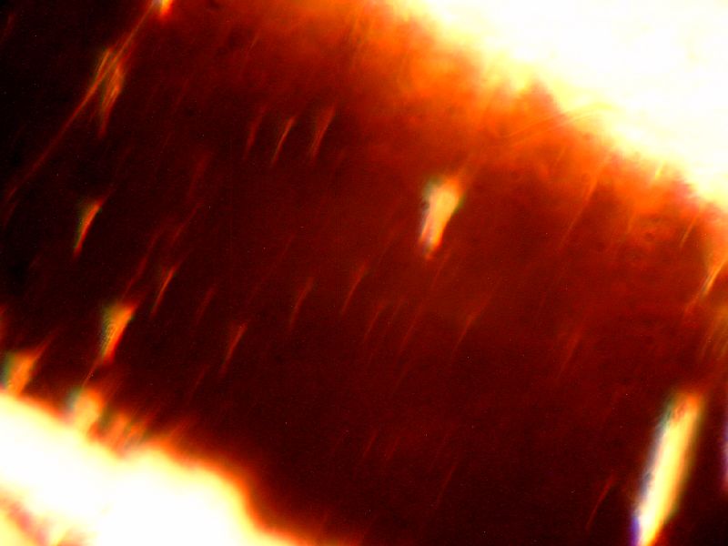
On sharpest focus it gives:
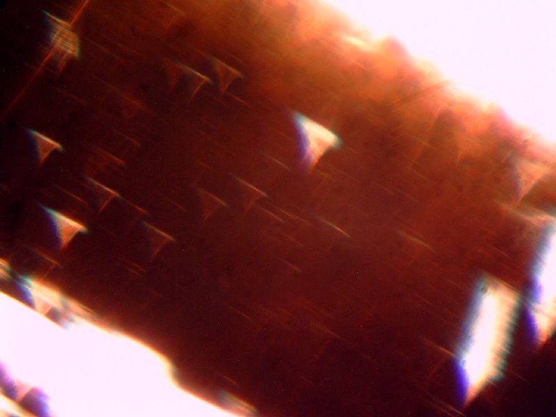
Adjusted too far:
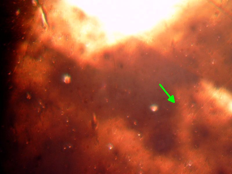
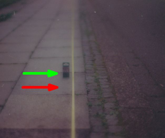
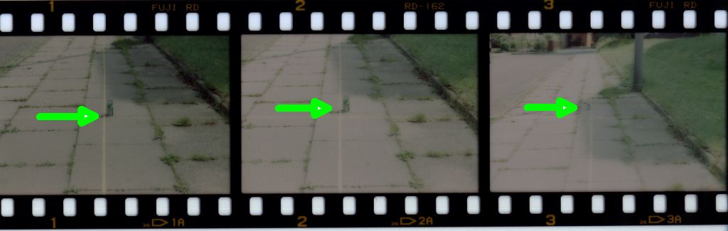
Note how the tiniest bright holes in the ink disappear when out of focus (e.g., green arrow). Bigger ones stay visible but get coloured halos. This tells a lot about the correction state of the lens. For an in-depth discussion, you should read Harold Suiter's book "Star testing astronomical telescopes". But this is unimportant for simply adjusting the camera. For photography, you will learn more if you stop down the lens and watch the improvement. I will never again use a lens at full aperture for critical work!
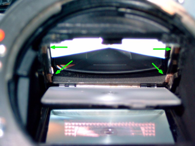
Above all, one has to compare the best focus when shutter open (looking at ink lines) and when closed (looking on focusing screen). The lens´ focusing position has to be identical! Mine wasn't. I had to focus the ink lines to closer a distance on the lens scale. This means that the film plane was too far away compared to the viewfinder. This is in accordance with my test pictures which showed a closer distance sharp than that focused on. But before filing the camera thinner, I checked the picture quality in all four edges of the film plane.
It is quite normal that sharpness decreases to the edges. But I was disappointed how much it was. The tiny holes in the ink were barely recognizable, and the brighter ones were smeared out to different focus-dependant figures. Here are some pictures of too short, best, and too far focus.
What I wondered about was that picture quality at best focus was quite different in different edges. Maybe something decentered? I tried several lenses and several bodies, without finding the cause. Finally I decided to live with that and instead try to fix at least those things I understand.
Two of the tested OM Bodies showed a big difference between centre screen focusing and centre of film plane. To find the exact value, I placed thin pieces of junk between film rails and my transparent plate. This enlarges only the lens-film plane distance. Household aluminium foil gave 6 um per layer, thick PE foil was 50 um, a piece of film 150 um. I ended up with 0,2 mm copper foil in one and 0,1 mm brass in the other camera. With that additional distance, focus was identical in viewfinder and on film.
Huh, what a tolerance. It's 5 and 10 times bigger than the maximum deviation allowed by the factory! I have not the slightest idea how this much can happen. Anyway, it has to be fixed. It would be a difficult task to lift the film rails by this amount. But the equivalent is, leaving the film where it is and moving the focusing screen by the same amount closer to the lens. You only have to put these thin foil pieces between the focusing screen plate and its seat in the camera body.
This starts just like changing the screen: On the top of the OM's bayonet mount opening, you see the bottom side of the focusing screen.
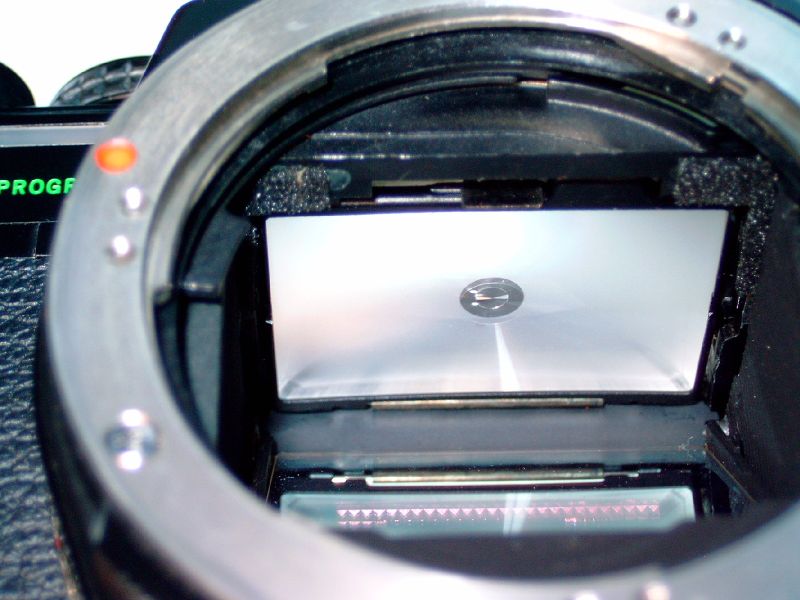
In the middle there is a metal strip, four millimetre wide. Pull it a little to the camera front, and the focusing screen together with its holding frame will tip down.
Now there are two options: either taking out the focusing screen and glueing the distance pieces to its edges, or to glue them into the camera, where the focusing screen is pressed on.
The first option is easier and can be undone simply by replacing the focusing screen. But it works only for one screen, which is then ruined for everything else. And if it is changed, the adjustment will be lost. Therefore I tried the second solution. I made four pieces of about 1,5x3 mm of the above material of appropriate thickness. It's tricky to get them in the right place, near the corners of the metal frame below the prism, without getting glue on the meter needle or the prism, and without them protruding into the viewfinder image area. A pencil with a tiny blot of chewing gum or similar sticky substance on its tip is a useful tool for handling those little distance pieces. The glue has to be as thin as possible. For the metal strips, I used a very liquid cyan-acrylate glue which hardens within a couple of minutes, applied with a needle tip before inserting them. For the paper ones, it was a water-soluble paper glue. Here's the result:
After cleaning everything from possible traces of spilled glue, the screen can be reassembled and the camera is ready for testing. Again the crucial proof is that viewfinder and ink lines on plate both have to be sharp without re-focusing. In my case, the improvement was drastic, on both OM bodies adjusted this way. Now these cameras photograph exactly that distance sharpest that is focused on. If I had access to a good film scanner, the pictures below would show that:
But the above cure does not correct the wrong lens mount-film plane distance. It is still possible to focus "beyond infinity", that means, to get things sharp that are several kilometres away, I can't simply turn the lens up to its infinity stop. The sharpest position is a bit closer on the lens' scale. But since the vast majority of my subjects are only a few metres apart, I decided to live with that. If I ever start doing astrophotography, I will have to improve on that. For a method how to do this, read on about my third camera body.
Adjusting the lens-to-film-distance
On this body, the telescope test set-up revealed that viewfinder and film plane were almost in accordance. But I had to readjust lens focus for every edge of the picture area. So there was a difference in sharpness from one side to the other, as if something was tilted. Furthermore, I found that on the very top of the image area, I couldn't focus far enough to get the image sharp! Since this affected both viewfinder and ink lines the same way, something must be wrong in front of the mirror. This is how to fix it:
The easiest way is to adjust the lens mount. First unscrew the three screws marked green with a #00 screwdriver for only a fraction of a turn. Their heads should not come out higher than the lens mount's surface. One can feel this with a fingertip.
When the lens is mounted back on its place, it can now be tilted by a minute amount. Back in the test set-up, we can now study the effects. It is easily seen which side(s) have to be lifted to distribute the sharpness more equally in all edges.
If you are good in optics, you may estimate already from focusing which edge has to be made higher or lower. If you have to turn the lens to bigger distances, then this edge is too close. Additional distance is needed on this side. I did this wrong more than once and had to repeat everything half a dozen times...
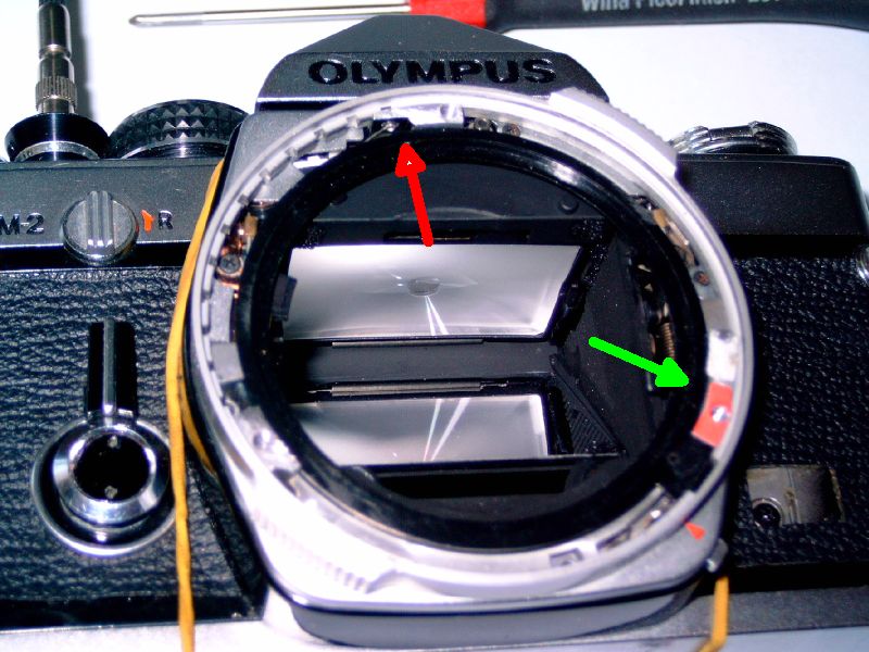
Suppose now we are sure where to correct something. The three screws in the bayonet mount have to be taken out completely. Now lift off the bayonet mount, while holding down the exposure time ring. This gets easier by putting a knife or fingernail between them. Take care not to lift off the two black plastic rings inside which operate the iris diaphragm. There are tensioned white strings attached to them (upper green arrow. The lower arrow points to the place where the black rings are connected to the speed ring.).
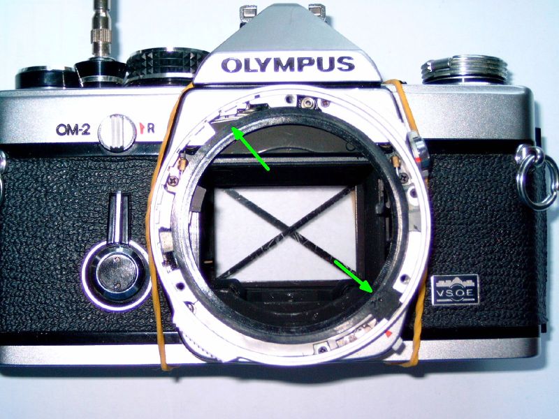
If the strings get loose, you have to dig really deep into the bowels of your camera to put them back in place ;-) Hopefully you don´t need this.
Now back to lens mount adjustment. If an extra distance is needed because the lens has to be focused to a bigger distance, simply put thin strips of paper, foil etc. on the posts where the lens mount sits on. A hole has to be poked through them where the screw hole is (green arrows in the following two pictures).
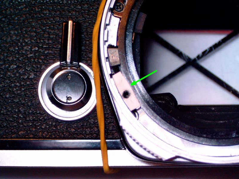
Much harder is when the lens-film distance is already too big. This was the case on the upper post (red arrow). It had to be lowered by several hundreds of a millimetre. For better access, the time ring has to be lifted off, too. Again, hold down the inner black plastic rings to which those white strings are attached!! Also take care of the little steel ball (top of red arrow) which makes the time ring click when turning. It falls out easily.
I simply filed down the upper post. Placing the nozzle of a vacuum cleaner close to the camera prevents dirt from falling into the camera. A few strokes with a fine file were enough since the post is made of aluminium. Some care is needed to keep the surface flat, without the edges getting too low. Scraping with a sharp knife removes remaining burrs.
Now time ring and lens mount can be reassembled. Tightening the three screws is very critical, as the lens mount tilts a bit depending on the order of the tightening. So, if a new test still shows unequal sharpness over the image area, first try to tighten the screws in different order, before disassembling everything again.
I needed three iterations with filing, paper strips and telescope testing to get it right. (Some additional times were due to my errors.)
But finally, the viewfinder and test plate now agree in sharpness when tested with the telescope set-up, at least to a level which I can live with. There are still minute differences between centre and film edges, but they change a lot with the lens in use. Most lenses are so bad at the corners that the remaining adjustment errors are negligible.
I spent a lot of time with this because I had to invent and learn much. Maybe you can do faster after reading the above story. You may gain better focusing and sharper pictures.
Only testing your camera involves little risk. But I would not recommend doing the adjustment to anyone who is afraid of ruining a camera!
In my case, I had to disassemble one camera body completely, and after putting it together again the “auto exposure” mode did work erratically. Maybe this will be my next story...
-der uli Sept. 2009