Removing the OM-1/OM-2 Top Cover


One of the most asked questions when trying to repair an OM body is "How do I remove the top cover?". The exact procedure for removing the top cover is different for each OM model, although the general idea remains the same. The procedure described here applies only to the OM-1 and OM-2 bodies.

Tools Required

Before we begin you will require some basic tools to properly perform the top cover removal. Warning, failure to use the proper tools will likely results in either scratching the camera's surface, or in the worst case, damaging the part you are trying to remove. OM-1 and OM-2 replacement parts are no longer available so extra care should be taken when working with these older bodies. Good quality tools are not expensive and are easily purchased via numerous on-line retailers. The time and money invested in acquiring a good set of tools will easily pay for itself.
 
Tools
Click on photo for a larger image
The tools required for removing the top cover are:
  • A good quality gum rubber stopper or similar tool
  • A spanner wrench with pointed tips
  • An old 35mm film spool (ask your local photofinisher for a few, they'll be glad to get rid of them)
  • A set of pointed tweezers
  • A #00 cross point screwdriver (a phillips point will probably be ok)
  • A small case to hold the removed parts

Step 1: Removing the Wind Lever

Wind Lever Removal
Click on photo for a larger image
The wind lever on an OM-1/OM-2 is held on using a cap screw. Although there are two holes present in the cap screw, DO NOT use any tools such as tweezers or spanners in those holes to remove the cap screw. You will damage the trim plate if you use such tools. Replacement trim plates are no longer available so you will have to live with whatever damage occurs.
 
A much better and safer method of removing the cap screw is to use a large rubber stopper. A good quality gum rubber stopper will provide enough friction to unscrew the cap screw without damage. Some cap screws may be very tight and will require a significant amount of downward pressure before they will unscrew. It's a good idea to clean the surface of the rubber stopper with acetone or a similar solvent to help increase the "stickiness" of the rubber stopper.
Wind Lever Parts
Click on photo for a larger image
Once the cap screw has been removed, the plastic trim plate and the wind lever will be loose and can be removed from the shaft. Take them off and set them aside.
Wind Lever Removal
Click on photo for a larger image
Underneath the wind lever you will find a circular retaining ring. You will need to use the spanner wrench to remove this ring. Take care not to push down too hard on the spanner as the holes in the ring are not very deep and the spanner tips will bottom out and may scratch the underlying metal.

Step 2: Removing the Rewind Knob

Rewind Knob Removal
Click on photo for a larger image
The rewind knob is screwed onto the shaft which protrudes into the body. Do NOT attempt to remove the screw which is visible when the rewind handle is opened. This screw does not hold the knob onto the shaft, it merely acts as a resting platform for the handle when it is closed. The rewind knob is reverse threaded onto the shaft so that as the film is rewound into the cassette, the knob is tightened onto the shaft. To remove the rewind knob we must hold the shaft while turning the knob counter clockwise. The shaft is made of very soft brass and can easily become bent if held with too much pressure, or if an object is inserted between the forks. A simple tool to safely hold the shaft can be manufactured using an old 35mm film spool. Insert a screwdriver into the plastic spool so that it can be prevented from rotating. Put the spool with screwdriver attached into the body and turn the rewind knob counter clockwise while preventing the film spool from rotating. The rewind knob should begin to unscrew. Remove it and set it aside.
Rewind Knob Removal
Click on photo for a larger image
Under the rewind knob you will find two screws. Remove these screws and set them aside in the parts canister (don't leave them on your bench, they tend to grow legs and wander off :-)

Step 3: Removing the Flash Socket Retaining Ring

Wind Lever Removal
Click on photo for a larger image
The retaining ring which holds the flash shoe bracket to the top cover can usually be unscrewed with a small set of tweezers. If the ring is on very tight, carefully use the spanner to remove it. In either case be very careful not to push down too hard as the tips of the tweezer or spanner will scratch the top cover. Set the ring aside in the parts canister.

Step 4: Taking the Top Cover Off

Latch Spring
Click on photo for a larger image
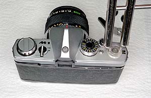
Once the advance lever, rewind knob, and flash shoe bracket ring are removed, the top cover can easily be lifted off the body. Begin by gently pushing upwards on each corner of the cover while rocking the cover side to side. With a few back and forth rocking motions the cover will begin to separate from the body and can be lifted off. 
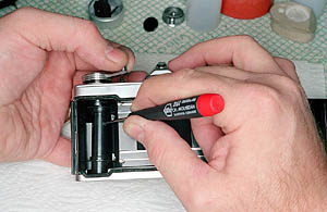
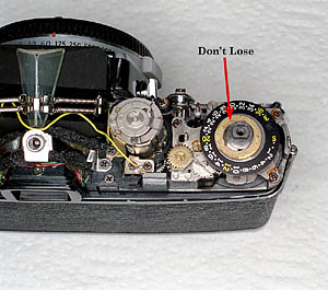
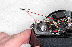
Warning, there are a few loose pieces under the top cover. Make sure you lift off the top cover with the camera sitting upright.
 
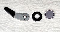
Once the top cover has been removed, remove the door latch spring from the door latch and set it aside. You will also find several loose pieces around the flash shoe socket. The exact pieces around the flash shoe socket will vary depending on the body model. Make a note of the order of the loose pieces as you remove them and set them aside.
Wind Washer
Click on photo for a larger image
There will also be a loose piece around the wind shaft. The exact type of piece will depend on the vintage of the body which is being opened. On the oldest bodies you will find a thin brass washer as shown in the photo. In newer bodies there will be a small washer located at the very top of the shaft. Remove whichever piece is present and set it aside.

Re-installing the Top Cover

Meter at ASA
Click on photo for a larger image
Re-installing the top cover is mostly just the reverse order of the above disassembly procedure. The only additional step involves ensuring correct alignment between the top cover ASA dial and the meter. Problems will arise if the tab on the meter housing doesn't align with the slot in the ASA dial. The easiest method of ensuring correct alignment is to set both the meter and the dial to 100 ASA. The dial is easily set to 100 ASA using the controls present on the top cover. The meter is set to ASA 100 when the indicated line on the meter is directly above the indicated cam (see accompanying photo). When the top cover is replaced, the meter and the ASA dial should line up.

Next: removing the pentaprism foam......


Last update: October 1, 2003 Mark Dapoz
md@dementia.org

©copyright 2003 by Mark Dapoz. This material is provided free for personal use only. Redistribution or resale, either in part or whole, is strictly prohibited.